Cable Sizes
|
Conductor area / CPC area (mm²) |
Current carrying capacity (A) for various reference methods (see table below) |
Conductor dia (mm) |
Outer PVC size (h x w)(mm) |
||||||
|
A |
B |
C |
100 |
101 |
102 |
103 |
|||
|
1 / 1 |
11.5 |
13 |
16 |
13 |
10.5 |
13 |
8 |
1 x 1.13 |
4.5 x 8.2 |
|
1.5 / 1 |
14.5 |
16.5 |
20 |
16 |
13 |
16 |
10 |
1 x 1.38 |
4.7 x 8.2 |
|
2.5 / 1.5 |
20 |
23 |
27 |
21 |
17 |
21 |
13.5 |
1 x 1.78 |
5.3 x 9.9 |
|
4 / 1.5 |
26 |
30 |
37 |
27 |
22 |
27 |
17.5 |
7 x 0.85 |
6.1 x 11.4 |
|
6 / 2.5 |
32 |
38 |
47 |
34 |
27 |
35 |
23.5 |
7 x 1.04 |
6.8 x 13.1 |
|
10 / 4 |
44 |
52 |
64 |
45 |
36 |
47 |
32 |
7 x 1.35 |
8.4 x 16.8 |
|
16 / 6 |
57 |
69 |
85 |
57 |
46 |
63 |
42.5 |
7x 1.71 |
9.6 x 19.5 |
Installation Methods
The current carrying capacity of any cable is dictated by its maximum conductor temperature, and this in turn will be affected by its ability to dissipate heat. The way it is installed can have a significant effect on this ability. The following table explains the methods cited above. The number of installation methods described in Table 4A2 (previously 4A1) has risen from 20 to 50-odd. Although this may appear to make things more complicated, the appendix now embraces installation methods that are used but which were not previously accounted for, including installation methods in building voids, direct in ground, in ducts in the ground, and flat twin and earth cables in thermal insulation. It is impractical to calculate and publish current ratings for every installation method, since many would result in the same current rating. Therefore a suitable (limited) number of current ratings have been calculated which cover all of the installations stated in the Wiring Regulations, and are called reference methods. All the individually numbered installation methods have a lettered reference method stated against them in Table 4A2, except for flat twin and earth cables which have reference method numbers 100 to 103. There are seven alphabetically lettered reference methods, that is A to G.
|
BS7671 17th Editon Reference Method |
Example of installation method |
BS7671 16th Edtn Reference method |
BS7671 17th Edtn Installation method |
| A | In conduit in an insulated wall with the conduit close to or touching the inner skin. | methods 4 & 6 | methods 1 & 2 |
| B | Enclosed in conduit or trunking on or in a wall. 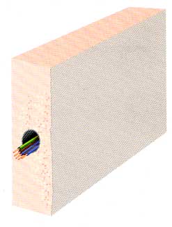 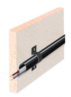 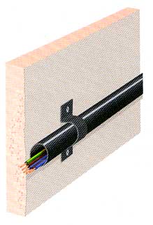 |
method 3 | methods 4 & 5 |
| C | Clipped direct, or sheathed cables embedded directly in masonry, brickwork, concrete, plaster or the like (other than thermally insulating materials)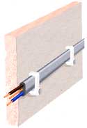 |
method 1 | method 20 |
| 100 | Above a plasterboard ceiling covered by thermal insulation, insulation thickness <100 mm. 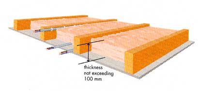 |
15 | method 100 |
| 101 | As above but with insulation thickness >100 mm. 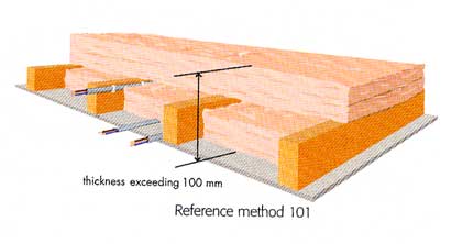 |
15 | method 101 |
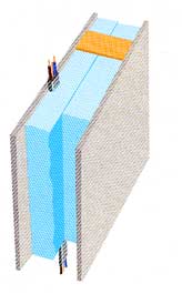
| 102 | In a stud wall with thermal insulation with the cable touching the innerwallsurface.
|
15 | method 102 |
| 103 | In a stud wall with thermal insulation with the cable NOT touching the inner wallsurface.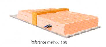 |
15 | method 103 |
Reference methods not included in the table are.
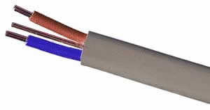
T&E current carrying capacity
Note The current carrying capacity values given for the various cable sizes above are only correct for the fixing methods listed. They are also only correct for a single cable not in close proximity to any other cables. For all other installation methods not covered above, the values stated will be incorrect. To find the correct rating in these circumstances the quoted current carrying capacity listed in columns C (i.e. method 1) will need to be “de-rated”. This means that correction factors need to be applied to the current carrying capacity in order to factor out these environmental effects that otherwise could result in cable overheating (and hence overloading) if ignored. In addition to the fixing method, there are other correction factors that will effect the rating:
For full details of the de-rating factors and more detailed version of current carrying capacity table, see table 4D1A in appendix 6 of the On Site Guide.
Typical T&E Cable Applications
|
Cable Size (mm²) |
Typical Applications |
|
1.0 |
lighting circuits |
|
1.5 |
high power lighting circuits, 16A Radial power circuits |
|
2.5 |
32A Ring final circuits, 20A Radial circuits |
|
4.0 |
32A Radial circuits, Cooker circuits, low power electric showers |
|
6.0 |
Small Sub mains, Radial circuits for showers, high power cookers, and other high power devices |
|
10.0 |
Sub Mains, Radial circuits for high power showers, cookers, and other very high power devices |
|
16.0 |
Sub Mains |