Modern mains cable
This article describes the main characteristics of most of the different types of cable that is currently used in domestic installations and that we use on a daily basis.
The following have their own articles:
T&E (Twin and Earth)
This is the most common cable used for domestic wiring today.
PVC-sheathed T&E cable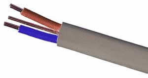
- Live and neutral are individually insulated, and the Circuit Protective Conductor (CPC) (aka earth) is bare
- There is an overall sheath of grey PVC (BS 6004), or white for low smoke compound (BS 7211)
- Not suitable for unprotected use outside (outer sheath materials are vulnerable to attack by UV radiation)
- 1mm² 1.5mm² & 2.5mm² have solid (non-stranded) conductors
- 4mm², 6mm², 10mm², 16mm² and higher have stranded conductors
Cable Sizes
|
Conductor area / CPC area (mm²) |
Current carrying capacity (A) for various reference methods (see table below) |
Conductor dia (mm) |
Outer PVC size (h x w)(mm) |
||||||
|
A |
B |
C |
100 |
101 |
102 |
103 |
|||
|
1 / 1 |
11.5 |
13 |
16 |
13 |
10.5 |
13 |
8 |
1 x 1.13 |
4.5 x 8.2 |
|
1.5 / 1 |
14.5 |
16.5 |
20 |
16 |
13 |
16 |
10 |
1 x 1.38 |
4.7 x 8.2 |
|
2.5 / 1.5 |
20 |
23 |
27 |
21 |
17 |
21 |
13.5 |
1 x 1.78 |
5.3 x 9.9 |
|
4 / 1.5 |
26 |
30 |
37 |
27 |
22 |
27 |
17.5 |
7 x 0.85 |
6.1 x 11.4 |
|
6 / 2.5 |
32 |
38 |
47 |
34 |
27 |
35 |
23.5 |
7 x 1.04 |
6.8 x 13.1 |
|
10 / 4 |
44 |
52 |
64 |
45 |
36 |
47 |
32 |
7 x 1.35 |
8.4 x 16.8 |
|
16 / 6 |
57 |
69 |
85 |
57 |
46 |
63 |
42.5 |
7x 1.71 |
9.6 x 19.5 |
Installation Methods
The current carrying capacity of any cable is dictated by its maximum conductor temperature, and this in turn will be affected by its ability to dissipate heat. The way it is installed can have a significant effect on this ability. The following table explains the methods cited above. The number of installation methods described in Table 4A2 (previously 4A1) has risen from 20 to 50-odd. Although this may appear to make things more complicated, the appendix now embraces installation methods that are used but which were not previously accounted for, including installation methods in building voids, direct in ground, in ducts in the ground, and flat twin and earth cables in thermal insulation. It is impractical to calculate and publish current ratings for every installation method, since many would result in the same current rating. Therefore a suitable (limited) number of current ratings have been calculated which cover all of the installations stated in the Wiring Regulations, and are called reference methods. All the individually numbered installation methods have a lettered reference method stated against them in Table 4A2, except for flat twin and earth cables which have reference method numbers 100 to 103. There are seven alphabetically lettered reference methods, that is A to G.
|
BS7671 17th Editon Reference Method |
Example of installation method |
BS7671 16th Edtn Reference method |
BS7671 17th Edtn Installation method |
| A | In conduit in an insulated wall with the conduit close to or touching the inner skin. | methods 4 & 6 | methods 1 & 2 |
| B | Enclosed in conduit or trunking on or in a wall. 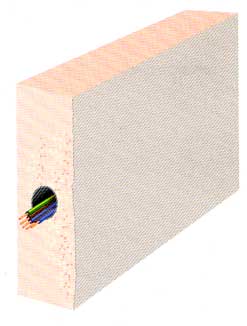 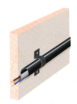 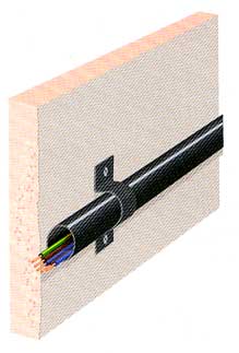 |
method 3 | methods 4 & 5 |
| C | Clipped direct, or sheathed cables embedded directly in masonry, brickwork, concrete, plaster or the like (other than thermally insulating materials)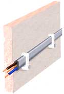 |
method 1 | method 20 |
| 100 | Above a plasterboard ceiling covered by thermal insulation, insulation thickness <100 mm. 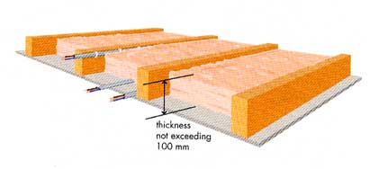 |
15 | method 100 |
| 101 | As above but with insulation thickness >100 mm. 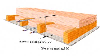 |
15 | method 101 |
| 102 | In a stud wall with thermal insulation with the cable touching the innerwallsurface.
|
15 | method 102 |
| 103 | In a stud wall with thermal insulation with the cable NOT touching the inner wallsurface.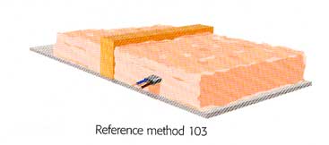 |
15 | method 103 |
- Methods 100, 101 and 102 require the cable to be in contact with the plasterboard ceiling, wall or joist
- Ratings (BS 7671 Table 4D5A (16th), or Table 4D5 (17th)) apply for ambient temperature of 30 deg.C and a maximum conductor temperature of 70 deg.C
- All the usual derating factors apply (see below and appendix 4 of BS 7671 or appendix 6 of the OSG).
- Current ratings are continuous.
- Outer cable sizes are guideline figures and can vary for different brands of cable of the same conductor size.
Reference methods not included in the table are.
- Reference method D – Direct in the ground or in ducting in the ground.
- Reference method E – Multicore cables in free air or on perforated trays.
- Reference method F – Single-core cable touching in free air or on perforated trays.
- Reference method G – Single-core cable spaced in free air or on perforated trays.
T&E current carrying capacity
Note The current carrying capacity values given for the various cable sizes above are only correct for the fixing methods listed. They are also only correct for a single cable not in close proximity to any other cables. For all other installation methods not covered above, the values stated will be incorrect. To find the correct rating in these circumstances the quoted current carrying capacity listed in columns C (i.e. method 1) will need to be “de-rated”. This means that correction factors need to be applied to the current carrying capacity in order to factor out these environmental effects that otherwise could result in cable overheating (and hence overloading) if ignored. In addition to the fixing method, there are other correction factors that will effect the rating:
- Ambient Temperature
- Covering in thermal insulation
- Grouping cables together
- Use of semi enclosed (rewireable) fuses
- Encapsulation in conduit or trunking
For full details of the de-rating factors and more detailed version of current carrying capacity table, see table 4D1A in appendix 6 of the On Site Guide.
Typical T&E Cable Applications
|
Cable Size (mm²) |
Typical Applications |
|
1.0 |
lighting circuits |
|
1.5 |
high power lighting circuits, 16A Radial power circuits |
|
2.5 |
32A Ring final circuits, 20A Radial circuits |
|
4.0 |
32A Radial circuits, Cooker circuits, low power electric showers |
|
6.0 |
Small Sub mains, Radial circuits for showers, high power cookers, and other high power devices |
|
10.0 |
Sub Mains, Radial circuits for high power showers, cookers, and other very high power devices |
|
16.0 |
Sub Mains |
3&E
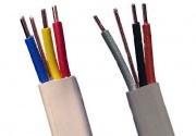 Three core and earth. Has three insulated conductors and a bare earth conductor.
In all other respects as T&E above. Typically used for two way lighting circuits, or other applications needing a permanent and switched live supply as well as neutral (e.g. feeding light switch activated extractor fans).
Also available in both PVC (BS 6004) and low smoke (BS 7211) versions.
Earth Sleeving
Earth sleeving is a plastic non 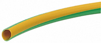 conductive tube that comes in a variety of diameters, 2 to 6 mm, to fit all types of cables, and is designed to fit over the bare earth conductor that comes with most types of cable.
Singles
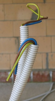
Singles in flexible conduit as pictured on the right.
- Insulated single conductors (larger sizes are stranded as per T&E table above)
- Standard cable for use in conduit
- Typically used in domestic work only for main & equipotential bonding
- Also available in both PVC (BS 6004) and low smoke (BS 7211) versions.
Tails
Very heavy gauge singles with two layers of insulation. Typically 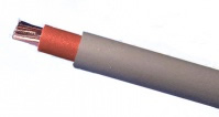 used for connections between electricity incomer, meter, and consumer units. Common sizes include 16, 25, and 35 mm². Commonly available from distributors as colour coded lengths in pairs. Older tails may only have a single layer of insulation.
LSF / LSH / LSZH
Low Smoke & Fume, Low Smoke & Halon, or Low Smoke Zero Halogen.
Most network cables are insulated with polyethylene, PVC or Thermoplastic Urethane (TPU) . In a fire, a halogen-containing plastic material releases a poisonous gas, e.g. hydrogen chloride, that forms hydrochloric acid when it comes in contact with water. Designated Halogen-free cables, on the other hand, do not produce a dangerous gas/acid combination or toxic smoke when exposed to flame.
Low smoke zero halogen cable reduces the amount of toxic and corrosive gas emitted during combustion. This type of material is typically used in poorly ventilated areas such as aircraft or rail cars. Low smoke zero halogen is becoming very popular and, in some cases, a requirement where the protection of people and equipment from toxic and corrosive gas is critical.
Other benefits of halogen free cable include:
- It is often lighter, so overall cable network system weights can be reduced.
- The environmental impact of halogen free cabling can be lower if there are fewer toxic chemicals.
- Low smoke versions of commonly available PVC cables are readily available.
e.g. BS 7211 for the PVC-sheathed BS 6004, and BS 6724 for the PVC-sheathed BS 5467.
SWA
Steel wire armoured.
A robust cable frequently used for 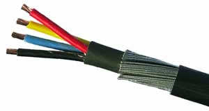 exterior wiring, where it may be buried directly into the soil, or suspended from a catenary wire. It consists of a number of individually insulated conductors covered next with a flexible bedding, then by a spiral screen of galvanised steel wires, and finally by a tough outer sheath. The insulating materials used typically being PVC or XLPE thermosetting plastic (the latter having a higher temperature rating, hence allowing the cable to carry a larger maximum current for a given conductor size). PVC Sheathed version if to BS 6346, XLPE-sheathed version is to BS 5467, and the low smoke version is to BS 6724.
- For outdoor & garden use.
- Available in 2, 3, 4, & 5 core versions.
- Must be terminated using the correct glands.
- May use the steel wire armour for the circuit earth / CPC in place of, or in addition to a core.
Cable Sizes & current carrying capacity (stranded copper conductors) BS 5467 XLPE Insulation
|
Conductor area (mm²) |
Current carrying capacity (A) |
Overall diameter (mm) |
|||||
|
2 core |
3 or 4 core |
2 core |
3 or 4 core |
2 core |
3 core |
4 core |
|
|
1.5 |
21 |
18 |
27 |
23 |
12.1 |
12.8 |
13.3 |
|
2.5 |
28 |
25 |
36 |
31 |
13.6 |
14.1 |
15.0 |
|
4 |
38 |
33 |
49 |
42 |
14.7 |
15.3 |
16.4 |
|
6 |
49 |
42 |
62 |
53 |
15.9 |
16.6 |
18.7 |
|
10 |
67 |
58 |
85 |
73 |
18.0 |
19.5 |
21.1 |
|
16 |
89 |
77 |
110 |
94 |
20.4 |
21.6 |
23.4 |
MICC
Mineral Insulated Copper Clad Cable.
Renowned for having good fire resistance and also a smaller cross section for a given current carrying capacity than other cable types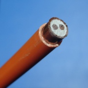
- aka pyro (from makers name Pyrotenax)
- Copper tube sheath with magnesium oxide insulation
- Fireproof
- Rigid
- Occasionally seen in domestic premises, mainly in blocks of flats
- Widely used for fire alarm systems in commerce
- Unterminated ends prone to absorbing moisture from the air
- Special cable terminations required
- Ideal for flammability risk areas, eg traversing a thatched roof.
- Picture shows 1.5 mm² MICC with outer diameter 7.2 mm
MICC is one of the toughest of cables because:
- its metal cased
- it handles very high temperatures
- it still works even if you hammer it quite flat – the conductors and mineral insulation all compress in the same proportion, and you have to go a long way before it shorts out
Hi Tuff
A PVC cable 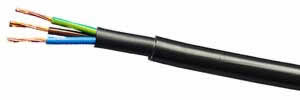 that is more robust than standard PVC sheathed cables and is suitable for general power, control and fixed wiring uses. An alternative to SWA for outdoor applications when direct burial of the cable is not required.
- Temporary wiring on open sites.
- Lighter and more manageable than steel wire armoured cables and requires only nylon glands to install – factors which contribute to speed of installation and cost savings.
- Provided there is no specific requirement for additional metal protection such as steel wire armouring, it will meet the demands of the most arduous installation conditions.
- Will not ignite under extreme applied heat.
FP 200 and other Soft Skin Fire Alarm Cables
Introduced as an alternative to MICC cable, but not as robust (the sheathing will burn away but circuit integrity is maintained).
- Silicone compound insulation
- Overlapping internal metal screen and drain wire (CPC)
- Low smoke sheathing material
Concentric cables
Neutral and earth conductors are arranged distributed around the central live conductors. Mainly used for incomers.
- Like T&E but with no neutral conductor.
- Not a popular cable.
- Supplier
Usually used for lighting circuits, the wiring works like this:
The permanent lives and switched lives of the circuit use the single core and earth cable (6241Y if you want to google it).
This run starts from the MCB and loops between the lightswitches to provide a permanent live and earth to the lightswitchs. Another length of 6241Y is then used from the lightswitch to the light fitting to provide a switched live and earth at the lightfitting.
The neutral cable is a double sheathed cable (6181Y with a blue inner sheath) that runs from the CU neutral busbar and from lightfitting to light fitting (there will only be one neutral at the end of the circuit).
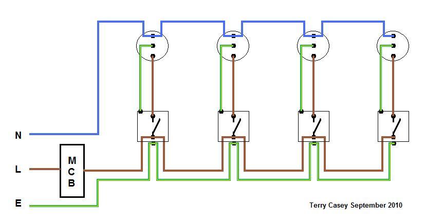
It makes it easier to put light fittings up as there are less cables to mess with at the fitting.
Voltage Drop
Any design must ensure the maximum voltage drop allowed between source and point of use is not exceeded when at full load. In the 16th edition this as 4% of the nominal supply voltage (about 9.2V at 230V AC). The 17th edition (in force from 1 July 2008) limits this to:
- 3% for lighting
- 5% drop for other loads
- (but 6% and 8% respectively are permitted for private supplies)
|
Conductor CSA (mm²) |
PVC (max 70° C) Voltage drop mV/A/m |
XLPE (max 90° C) Voltage drop mV/A/m |
|
1.0 |
44 |
46 |
|
1.5 |
29 |
31 |
|
2.5 |
18 |
19 |
|
4.0 |
11 |
12 |
|
6 |
7.3 |
7.9 |
|
10 |
4.4 |
4.7 |
|
16 |
2.8 |
2.9 |
These figures are presented for SWA cable here. The values quoted will usually also be correct for other copper cable types. Figures will differ slightly for cables with higher operating temp limits, such as MICC. The length figure above is per length of cable, not per each conductor.
These figures assume that the cable is operating at or near its maximum operating temperature. In designs where the maximum current load is significantly less that the capacity of the cable then these figures will be somewhat pessimistic. For these circumstance, it would be more appropriate to calculate voltage drops based on table 9A of the official I.E.E. “On Site Guide”.
Calculation Examples (PVC SWA):
1) 20m of 4mm², maximum load of 30A would drop 20 x 0.011 x 30 = 6.6V
2) 40m of 6mm², maximum load of 45A would drop 40 x 0.0073 x 45 = 13.14V
3) 10m of 1.5mm², maximum load of 16A would drop 10 x 0.029 x 16 = 4.64V
(1) and (3) are adequately specified with respect to voltage drop. However (2) is out of spec and a larger cable will need to be selected, even though the current handling capacity of the 6mm² cable has not been exceeded. Upgrading to 10mm², gives a result of 40 x 0.0044 x 45 = 7.92V which is acceptable. It initially appears that this still only leaves just over 1V of remaining drop available for any following wiring, however since we will not be operating the larger cable anywhere near its maximum temperature, the situation is actually less tight than the calculation suggests.
Conductor Colours and Harmonisation
Historically the UK used its own set of colour codes for fixed and flexible wiring. In the early 1970s the colours used for flexible wiring were harmonised across Europe, however the colours for fixed wiring remained unchanged until recently. In March 2004 the fixed wiring colours were also harmonised. During a transition period that began on 31st of March 2004 and ended on the 31st March 2006, use of either colour scheme was acceptable. Now only the harmonised colours may be used. The result is that it is now possible to encounter installations that use both colour schemes, and hence great care must be taken to ensure conductors are correctly identified when carrying out any work.
|
Conductor Colour Coding (single phase T&E)Conductor |
Old UK Colour |
Harmonised Colour |
|
Live (Phase) |
Red |
Brown |
|
Neutral |
Black |
Blue |
|
Earth or CPC |
Green / Yellow Stripe |
Green / Yellow Stripe |
|
Conductor Colour Coding (three phase / Triple and Earth / SWA) |
||||||
|
Conductor |
Old UK Colour |
Harmonised Colour |
2 Core (T&E or SWA) |
3 Core (3&E or SWA) |
4 Core (SWA) |
5 Core (SWA) |
|
Live 1 |
Red |
Brown |
X |
X |
X |
X |
|
Live 2 |
Yellow |
Black |
X |
X |
X |
|
|
Live 3 |
Blue |
Grey |
X |
X |
X |
|
|
Neutral |
Black |
Blue |
X |
X |
X |
|
|
Earth (CPC) |
Green / Yellow Stripe |
Green / Yellow Stripe |
X[1] |
[1][2] |
[2] |
X |
Notes
- Earth wire in cable will be a bare conductor and will need green/yellow sleeving to be applied at point of termination.
- Earth wires are present in T&E or 3&E cables. Other cable types such as SWA or MICC will still need to be earthed, however this will be carried using the cable armour / screen.
There is an IEE leaflet explaining these changes. That is available here
Installations that are wired using cables to both colour schemes should carry a warning sticker (see example) on or near the consumer unit that statesand looks something like this:
|
CAUTION This installation has wiring colours to two versions of BS7671. Great care should be taken before undertaking extension, alteration or repair that all conductors are correctly identified. |
We employ reliable professionals who are trained to deal with all aspects of electrical faults. AA Electrical Services is a reputable installation, repair and maintenance service company covering the South East area. Our team of electricians provides you with maintenance of your electrical installation and appliances as well as a fast and reliable breakdown service. Recognising current British standards, our electrical engineers are NICEIC registered, Part P accredited and qualified to 17th edition standard, as certified by the Institute of Electrical Engineers (IEE). This enables us to offer the highest levels of professional service to you.